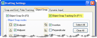
Object Snap Tracking
 r in relation to other objects. When you turn on Object Snap Tracking, by pressing F11 or clicking on Otrack on the status bar, it uses AutoCAD’s trademarked AutoTrack technology to create temporary alignment paths. This will help you create objects at precise positions and angles relative to a snapped object.
Object Snap Tracking works based on the current object snap settings. You must enable Osnaps before you can track from an object's snap point.
Move the cursor over the other line's endpoint to acquire it. You do not need to click on it, simply let it hover over the point until it is acquired. Acquired points display a small plus sign, shown in the figure above.
After you acquire a point, horizontal, vertical, or polar alignment paths relative to the point are displayed as you move the cursor over their drawing paths. You can acquire up to seven tracking points at a time.
Polar Tracking
Polar Tracking snaps the cursor to specified polar angles. You can use polar tracking to display temporary alignment paths defined by the angles you specify. In 3D views, polar tracking additionally provides an alignment path in the negative and positive Z (up and down) directions.
Polar angles are relative to the orientation of the current UCS and use that X orientation as the base 0 angle. As you move your cursor, alignment paths and tooltips are displayed when you move the cursor over the specified polar angles. Use the alignment path and tooltip to draw your object.
For example if you click on the Polar button in the status bar, right click and select Settings. Set the Polar Angle Settings to a 45-degree polar angle increment, an alignment path and tooltip are displayed when your cursor crosses the 0 or 45-degree angle. The alignment path and tooltip disappear when you move the cursor away from the angle and reappear near the next angle.
These can be quite handy when using the object snap tracking and polar tracking together. You can acquire the object snap tracking point and track at a polar tracking angle from that point.
Conclusion
There is a slightly different feel to using these commands. When you’re drawing, the cursor will have a lot more information floating around it. But once you get used to the new look and feel you’ll find that these commands can be a huge help. Try to take a little time to check out; you might be pleasantly surprised at what you find.


