The first panel on the left side of the Parametric tab is for the tools that create and modify geometric constraints. These are the relationships that are applied between two objects, points on objects, or between a single object and the coordinate system. In simple terms it works like an object snap that stays persistent throughout your design.
The middle sub panel on the Geometric constraints panel contains the commands that you will use to apply the constraints to objects in your drawings. These can be accessed from this location on the ribbon or with the GEOMCONSTRAINT command. There are twelve to choose from, we’ll cover each of them.

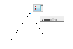
Coincident - Constrains two points on two objects together. A constraint point on an object can be made coincident with an object or a constraint point on another object. When the cursor hovers over the constrained point, the constraint bar to the right is shown.
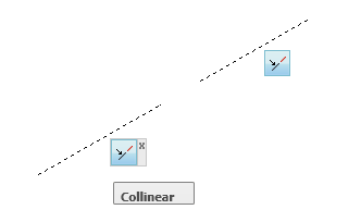
Colinear – Constrains two or more line segments to lie along the same line. Regardless of how the original line is moved or rotated, the Colinear line will move to match the new location.
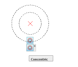
Concentric - Constrains two circles to the same center point. This also works for arcs and ellipses. The result is the same as that of a coincident constraint applied to the center points of the curves. Moving one of the circles will move the other with it, much like a block.
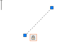
Fix - Locks a point or curve in position. The fixed point can be on an object, or a point in relation to an object, like a center point of a circle for example. This command may be a let down for those people who thought it might fix something in the drawings that doesn’t seem to work the way they wanted it to.
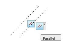
Parallel – Constrains two lines or polylines to be Parallel to each other. When one is modified the other will move to match it.
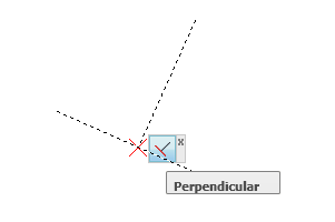
Perpendicular - Causes selected lines to lie 90 degrees to one another. Perpendicular constraints are applied between two objects and, unlike the Perpendicular object snap, these lines do not have to be touching each other when the constraint is created.
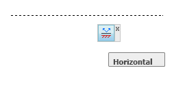
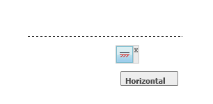
Horizontal - Causes lines or pairs of points to lie parallel to the X axis of the current coordinate system. Be aware when using this constraint that they are set to the axis in the coordinate system in which they were created. When another user coordinate system is active the Constraint bar icon (pictured below) will change to show that the current axis in not the one that the constraint was created in.
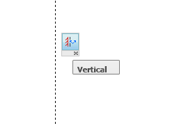
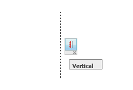
Vertical - Causes lines or pairs of points to lie parallel to the Y axis of the current coordinate system. Just like the Horizontal constrain these are set to the axis in the coordinate system in which they were created. When another user coordinate system is active the Constraint bar icon (pictured on the right) will change to show that the current axis in not the one that the constraint was created in.
Tangent - Constrains two objects to maintain a point of tangency to each other or their extensions. Tangent constraints are applied between two objects, those objects could be a curve (arc or circle) and a line or another curve.
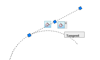
A circle can be made tangent to a line even if the circle does not touch the line and a curve can be tangent to another even if they do not physically share a point.
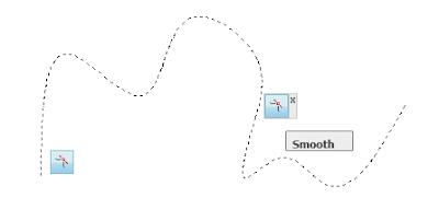
Smooth (G2) - Constrains a Spline to be contiguous and maintain continuity with another spline, line, arc, or polyline. When the constraint is applied the endpoints of the curves to which you apply the smooth constraints are made coincident.
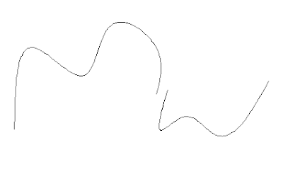
When two Splines are selected, they are updated to be contiguous with one another. This function is similar to using the JOIN command for polylines except the splines are not joined to be one object; they only behave as if they were one object.
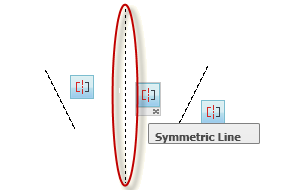
Symmetric - Causes selected objects to become symmetrically constrained about a selected line. The function is similar to that of the Mirror command. Unlike other constraints where two objects are selected, with a symmetric constraint you must have an axis around which you will constrain the objects or points to be symmetrical.
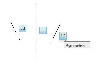
This is referred to as the symmetry line. For lines, the line’s angle is made symmetric and not the endpoints. For arcs and circles, the center and radius are made symmetric not the endpoints of the arc.
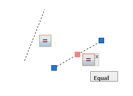
Equal - Resizes selected arcs and circles to the same radius, or selected lines to the same length.
